Hybrid Phono Preamplifier MK II
The Hybrid Phono Preamplifier MK II is an advanced version of its predecessor MK I. It has full MC capability, an
improved power source rejection ratio (PSSR), lower output impedance and needs 170V power supply voltage only. A
special feature is the battery grid biasing of the input tubes. With no current flow except for minuscule grid leakage
currents, battery life span will be limited predominantly by self-discharge. With lithium ion manganese oxide (LMO)
batteries life span may be up to 10 years. Interesting articles on triode battery biasing can be found here and here.
The MK II Circuit
Improved Power Source Rejection Ratio
The MK II Power Supply
The MK II Circuit (not yet built)
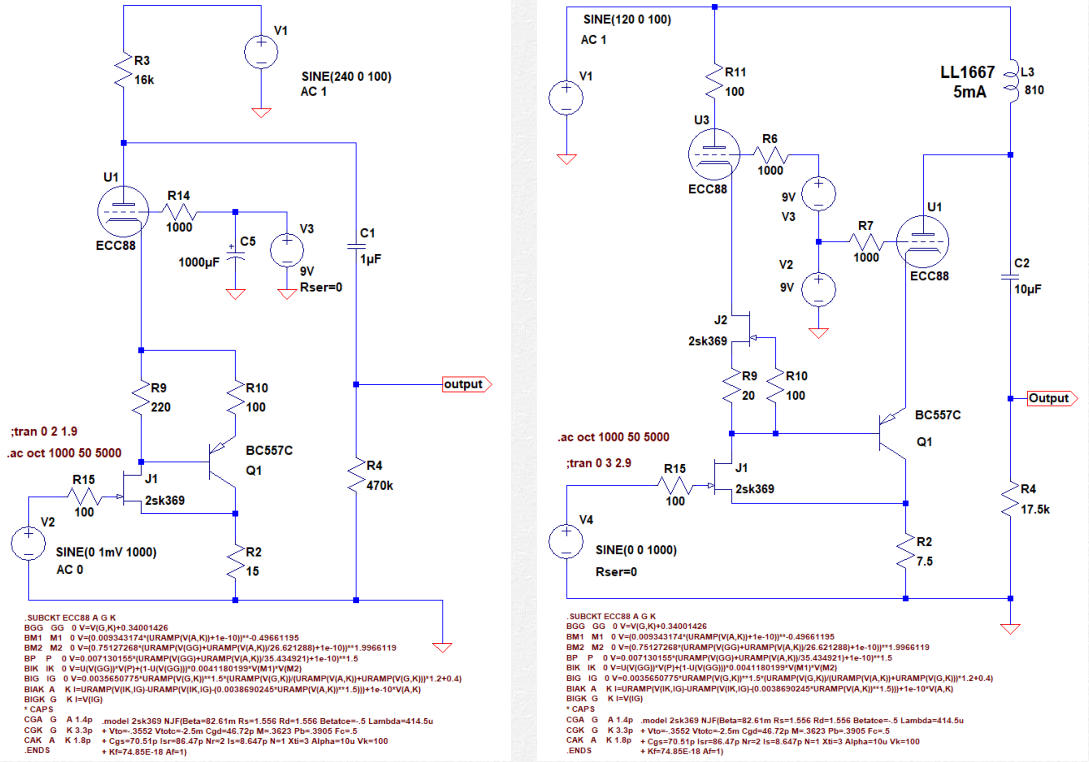
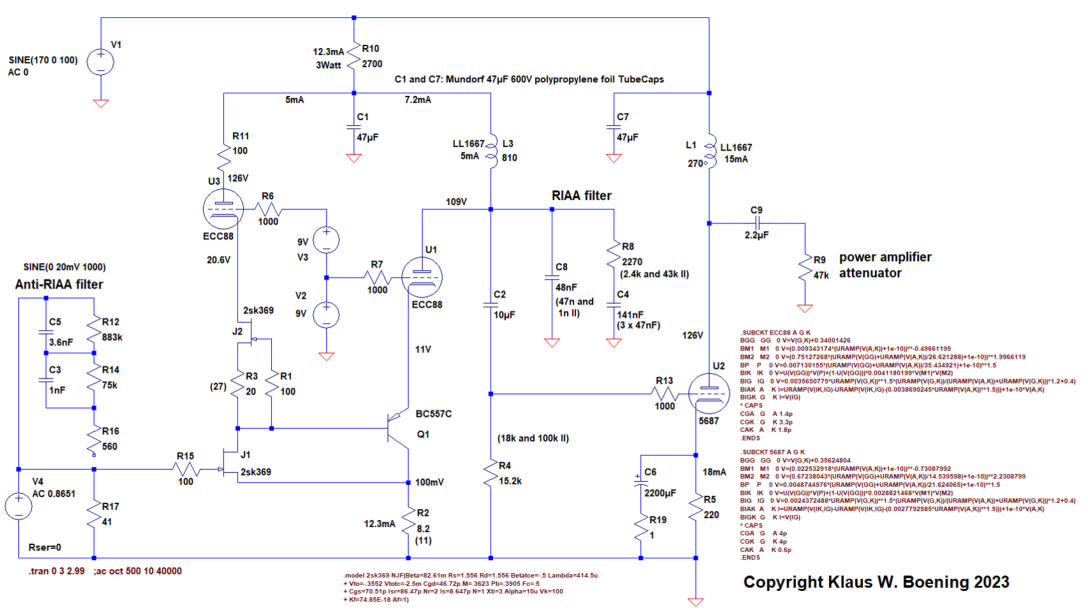
The below figure 1 shows the schematic. The drain of the 2SK369 input jFet (J1) is loaded by a current source (J2, R9,
R10), set to 5mA. Upstream an EC(C)88 (U3) provides a constant supply voltage of 21V. Both, J2 and U3 form a
cascoded current source and isolate the input jFet and the following BJT from potential noise on the the power
supply rail. Any current change of the input jFet is forced through the base-emitter diode of the following BC560C BJT
(Q1, BC557C in the schematic). The amplified signal current appears at the cathode of the second cascoding triode
(U1) and thus at its plate. The BJT / triode idle current is set to 7mA by R2. Two 9V batteries (V2, V3) elevate the ECC88
grid voltages to +9V and +18V respectively.
Plate chokes are used instead of plate resistors. The common 7mA idle current of Q1 and U1 passes through the
LL1667 (5mA) choke, while any signal voltage is fed into the RIAA network and the second stage via C2. According to
the manufacturer, the nominal choke idle current is 5mA. However, for the sacrifice of voltage swing headroom the
idle current may be exceeded up to 8mA (click here for more information). The choke and the resistor R4 form a low
pass filter (except for very low frequencies due to C2) and reduce noise from the power supply. A drawback is the
need of a large coupling capacitor C2. The capacitances right channel / left channel should be matched for C2 is RIAA
critical. Gain of the input stage is 67db (RIAA disabled).
Fig. 1: Schematic of the MK II phono stage with an anti-RIAA filter at the input. The two systems of the 5687 twin triode are shared
by the left and the right channel. All voltages and currents are taken from LT SPICE simulation.
The first stage is followed by a passive RIAA network. R4 as well as C2 are RIAA critical. Details on the RIAA
equalization network design can be found on the Laboratory Page of this web site. The simulated RIAA response is
within +/- 40mdb between 20Hz and 40kHz (Fig. 2).
Fig. 2: Simulated RIAA response is within +/- 40mdb between 20Hz and 20kHz.
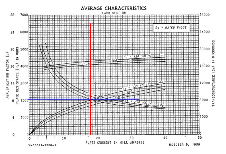
The second (output) stage uses the more powerful 5687 twin triode in a plain common cathode configuration. At
18mA idle current its plate resistance close to 2000Ohm (fig. 3). Still the voltage gain is sufficient. The plate is loaded
with a choke (LL1667,15mA). The DC load at the anode is 2400Ohm (copper resistance of the two coils in series). The
AC load is substantially higher due to the choke inductance of 270H. Thus the audio frequency load line of the triode
is almost flat. Alternatively an interstage LL1660 transformer might be used if ground loops are a problem or a
balanced output is needed. With an input voltage of 1mV @ 1000Hz the phono stage‘s output voltage is 3.2V in the
simulation. The phono stage easily can take 20mV
ss
at the input which would be 64V
ss
at the output.
Fig. 3: Plate resistance of the 5687 @ idle current of 18mA
Back to top of the page
Improved Power Source Rejection Ratio
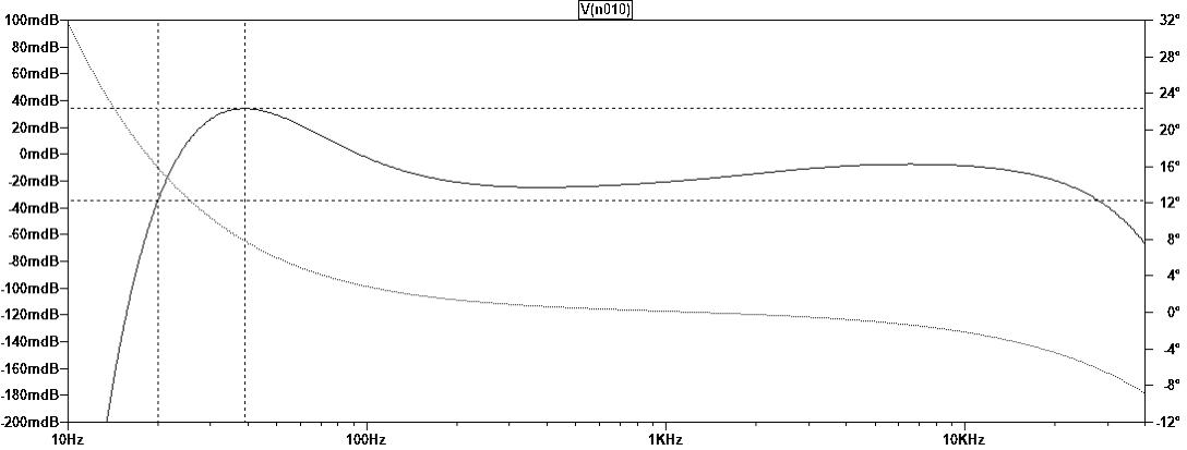
Simulations of PSRR were carried out on the MK I input design with a plate resistor (fig. 5) and the MK II design with a
plate choke (fig. 6). Sinusoidal interference voltages of 1V were were added to the supply voltages as frequency
sweeps from 50Hz to 5000Hz. Although the MK II design has twice the gain, its PSRR is considerably improved (fig. 7,
8). In real life the result might be even better, because the MK II design requires less power supply voltage and thus
should carry less 100Hz (or 120Hz) hum. Additionally the RIAA network will add some improvement on PSRR at
higher frequencies.
Fig. 4: MK I input stage without RIAA network Fig. 5: MK II input stage without RIAA network
Fig. 6:
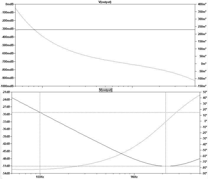
PSRR of the MK I input stage is -0.3db
with 1V AC interference voltage added to
the power supply voltage (50Hz to 5000Hz).
Fig. 7:
PSRR of the MK II input stage is
between -23db and -51db with 1V AC
interference voltage added to the power
supply voltage (50Hz to 5000Hz). At the
crucial 100Hz PSRR is -29db.
Back to top of the page
The MK II Power Supply
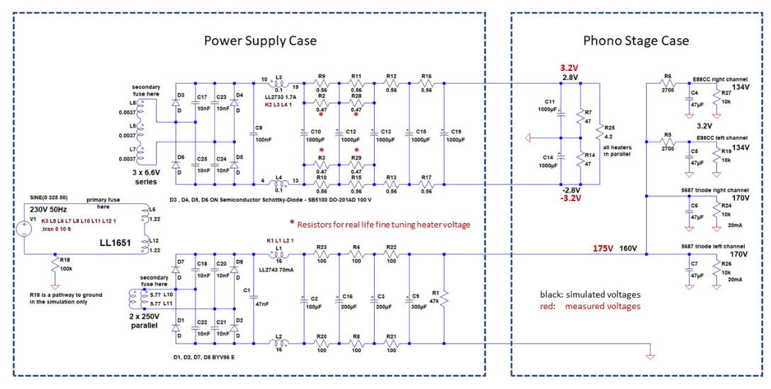
The power supply for the MK II hybrid phono stage is “old school” designed. The mains transformer is a grossly
oversized Lundahl LL1651 delivering 2 x 250V at its secondary coils. The two bridge rectifiers for the high voltage and
the heater voltage use fast recovery diodes and Schottky diodes respectively. The 10nF capacitors across the diodes
slow down voltage peaks from the rectifier switching noise transferring the energy towards lower frequencies.
Fig. 8: Power supply of the MK II hybrid phono stage. Transformer, rectifiers, chokes and most capacitors are mounted in a
separate housing. The information on the primary coil inductance of the LL1651 mains transformer is taken from the
Lundahl website and can be found here. Voltages in black are taken from LT SPICE simulations, voltages in red are actually
measured voltages.
Ripple currents are powerful sources of hum and buzz. Therefore, large reservoir capacitors are omitted to avoid
sharp current pulses. Instead, the rectified currents are fed into reservoir chokes (LL2733, LL2743) as the storages of
energy. Chokes try to maintain a constant current and block the AC components. They even provide some voltage
regulation. This is explained nicely in Merlin Blencowe’s book on Tube Preamps.
When the rectifier diodes switch off the chokes will generate flyback voltages. Therefore, two film capacitors (47nF
and 100nF) are placed immediately before the chokes. Each choke comprises two coils on a common core and are
wired in a common mode rejection configuration. Common mode noise may leak from other transformer coils via
stray capacitances and appear equally on both wires. The arrangement of the two choke coils block common mode
noise to a certain extent (click here and here for more information).
Downstream simple RC filtering is added for further smoothing – not particularly efficient but effective. R25
simulates the resistance of all paralleled heater filaments, R24 and R26 are dummy loads to simulate the 5687
triodes, R27 and R19 simulate the cascoded ECC88 triodes. Both, the heater voltage as well as the plate voltage leave
the power supply case as floating voltages without any reference to ground. Grounding is accomplished in the
amplifier case (fig. 8).
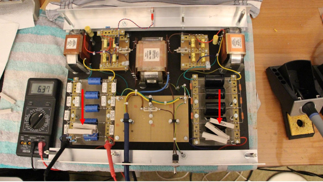
Fig. 9: Power supply of the MK II hybrid phono stage. The power resistors (red arrows) are dummy loads to simulate heaters
and plates.
Back to top of the page
to be continued . . . .