Laboratory Page Memphis MC 1
RIAA Equalization and Simulation
Several web sites with active or passive RIAA network calculators can be found on the internet. Mh-audio, KAB,
hagtech and others provide helpful calculators for passive RIAA networks. Obviously they all are based on the
equations published by Stanley Lipshitz in the 6/1979 Journal of the Audio Engineering Society and at least
these calculators are a good point to begin with.
A convenient way to evaluate the RIAA equalization in computer based simulations is to feed the virtual phono
signal through an inverse RIAA filter into the circuit. The resulting frequency response should be flat within the
tolerances accepted by the designer.
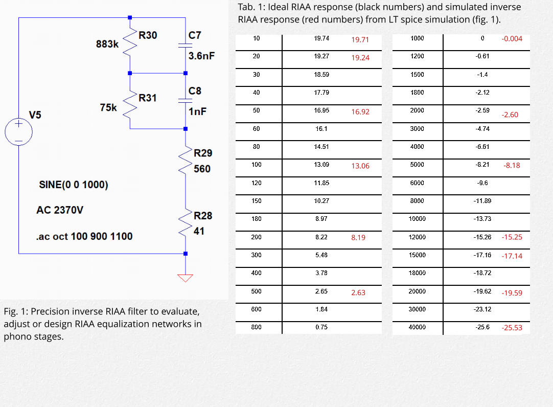
Searching the internet I found an interesting inverse RIAA filter (fig. 1) on the hifisonix web site. I simulated the
inverse RIAA equalization using LT spice and evaluated its accuracy by comparing the results from the
simulation (numbers in red) with the ideal RIAA response (tab. 1). Differences are between 0.01db to 0.03db
between 10Hz and 20kHz which might be considered sufficient. Thus I used this circuit as the anti-RIAA filter to
analyze and adjust the RIAA response of the Memphis MC1 phono stage (fig. 2).
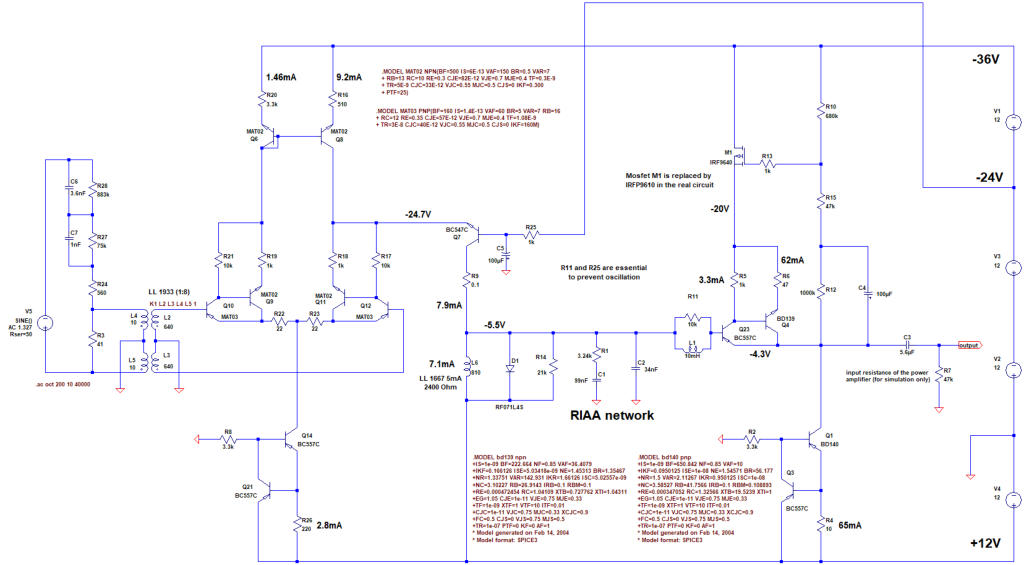
Fig. 2: Phono stage with inverse RIAA filter
Setting the values for the RIAA filter
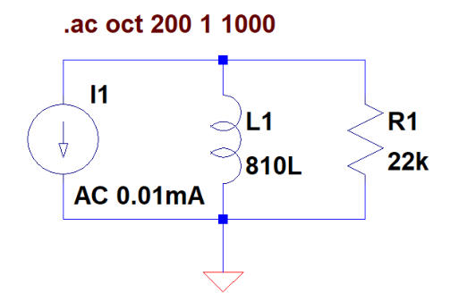
The Memphis MC1 RIAA filter is fed from a current source (transistor Q7) with L6 and R14 in parallel being the
load. A basic problem of this configuration is the limited low frequency response due to the choke. The
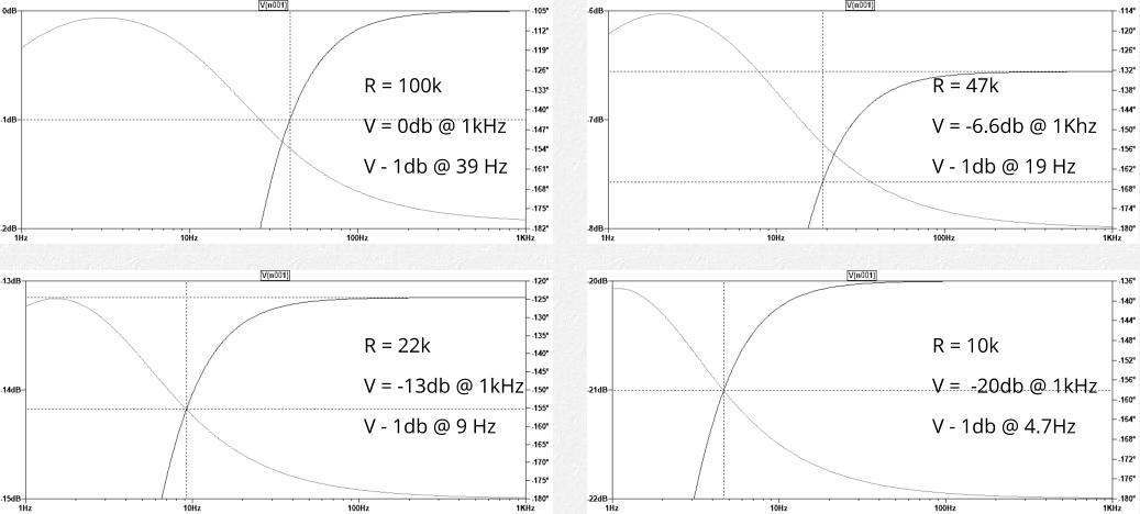
inductance of the LL1667 is 810H (copper resistance 2.4kOhm). The figures 3 to 7 show a simplified simulation
of the low frequency roll-off (-1db) with different standard resistor values of 100k, 47k, 22k and 10k in parallel
to the choke. As expected, the lower the resistor value, the lower the frequency at the -1db roll-off (39Hz @
100k, 4.7Hz @ 10k). On the other hand a lower resistance also decreases gain (0db @ 100k, -20db @10k). As a
compromise I accepted the -1db roll off @ 9Hz and chose a resistor around 22k as the basis for the further RIAA
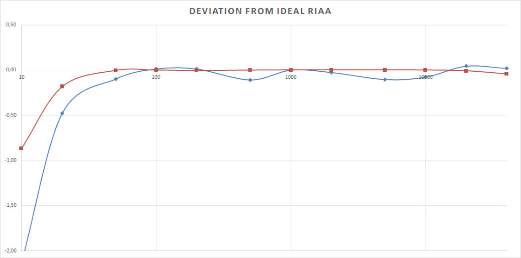
filter calculations. Figure 8 shows the simulated and the measured RIAA responses.
Fig. 3 to 7: Simulation of the low frequency roll-off
with R1 = 100k (4), R1 = 47k (5), R1 = 22k (6) and
R1 = 10k (7)
Fig. 8: Simulated (red) and measured (blue) deviations from the ideal RIAA response (db) between 10Hz and 40kHz with MC
input transformers and output capacitor included.
4
7
5
6
super triode, vinyl, audio, analog, single ended, SE, power amplifier, hybrid, tube, KT66, 6SN7, ECC88, Mosfet, Lundahl, MC phono stage, preamplifier, MM, MC, moving coil, moving magnet, LL1693, LL1667, LL9226, LL1933, RIAA, folded
cascode, 2CS5200, MAT12, 2N3810, LL1660S, IXFN32N120P, balancing amplifier