Memphis MC 1
Discrete Solid State Moving Coil Phono Stage
Full Circuit
Fig. 1: Full schematic of the new phono stage Memphis MC 1 (click to enlarge).
At first glance the schematic looks like a PNP overall concept with the negative voltage of -36V on top and the
positive +12V at the bottom (fig. 1). That results from the Sziklai configuration of both the first and the second
stage. However, at a closer look the more crucial transistors are all of NPN polarity. In the schematic the input
stage is set to suit a Ortofon Valencia Classic MC cartridge (output voltage 0.4mV). However, with a very few tweaks
the input stage can be modified easily to suit any other MC cartridge.
First Stage
A Lundahl LL1933 step-up transformer multiplies the MC output voltage by the factor eight. The differential input
design cancels out the base currents of the input transistors to keep the transformer free from any DC.
The two dual input low noise transistors 2N3810 (PNP) and MAT12 (NPN) are expensive but still reasonable
compared to New Old Stock (NOS) tubes. They are closely matched and of superb linearity. They are connected in a
Sziklai configuration. The current distribution through both transistors is determined by the ratios of the resistors
R17/R18 and R19/R21 respectively. The MAT12 dual transistor Q6 / Q8 is a current mirror with a 1:6.5 ratio. Q7
(BC550) resembles a folded cascode idling a current of 7.9mA. Its current is fed into the frequency depending load
L6, R1, R2, R14, C1, C2. The requested high gain of the input stage requires a high load impedance at the collector
of Q7. With 48V power supply voltage the 21k resistor (R14) alone would limit the collector current to a value below
1mA with respect to its voltage drop. This would severely compromise the signal amplitude of the input stage.
Therefore a choke (L6) is in parallel with the 21k resistor. Its inductance is 810H, its copper resistance is 2.4k. Thus
the DC load at the collector of Q7 is 2.4k in parallel with R14. The AC load is almost 21K at the low end of the audio
spectrum which then decreases with ascending frequency according to the RIAA equalization curve.
The LL 1667 choke is specified for 5mA idle current.
However, it can be used at higher DC currents
if its maximum AC voltage swing of 390V RMS is not
needed. Jac van de Walle (JacMusic) published a
very useful application note about DC currents an
corresponding maximum AC signal levels for the
LL1667 choke (tab. 1). In the phono stage the current
through the choke is set to 7.3mA.
Raw gain of the input stage (RIAA network R1, C1, C2 disabled) is 70dB plus the eightfold voltage step-up of the LL
1933 transformer. The input stage can easily be adapted to different gains by adjusting the degeneration resistors
R22 and R23. Furthermore the step-up transformer can be changed from a 1:8 to a 1:16 winding ratio if real low
output MC cartridges are favored. Figures 2 shows the first experimental setup.
Passive RIAA Equalization
Figure 3 shows the RIAA response. Contrary to standard voltage driven passive networks (fig. 4) the RIAA network
of the Memphis MC 1 phono stage is current driven, i.e. its signal comes from a current source with (almost)
infinite impedance. Thus the traditional circuit for a passive network has to be modified as shown in figure 5.
Details on the RIAA equalization network including a precision anti-RIAA circuit for SPICE simulation is described on
the Laboratory Page of this web site. Deviations from the ideal RIAA with reference to 0 dB at 1kHz is between
+0,17dB and -0.1dB between 30Hz and 40kHz (fig. 3). At 20Hz the response drops to -0.48dB below the ideal RIAA,
at 10Hz it is -2.1dB due to the limited inductance of the LL1667 choke.
Fig. 4 and 5: The impedance of the voltage source V1 is close to zero while the impedance of the current source I1 is close to
infinity. Thus C1, R1 and C2 "see" the same impedance of R3.
Second Stage
The second stage (fig. 1, fig. 7) is just an impedance converter with unity gain to
pass the audio signal as unaltered as possible from the RIAA network to the output.
It enables the phono stage to drive critical loads. The PNP/NPN Sziklai pair
input impedance is of several Megohm at the base of the transistor Q23 and does
not alter the RIAA equalization. The low-pass filter at the input (10K parallel with
10mH choke) suppresses RF oscillation (fig. 6).
Years ago Nelson Pass wrote in his article on cascode amp design: „ . . in real life, the gain of a transistor, tube or FET
changes as the voltage across the devices changes and as the current through the device changes. As these conditions
fluctuate, the device creates distortion, but if we hold these conditions to a constant, the device becomes distortionless.”
Therefore the p-channel MosFet on top is configured to bootstrap the transistors. Its source follows the output
signal. Thus the emitter / collector voltage across the Sziklai transistors is kept constant to reduce distortion. For
the same reason the output stage idle current is set to relatively high 65mA to reduce current changes with the
output signal to a miniscule fraction of the idle current. Figure 8 shows the maximum voltage swing of the phono
stage which is around 30V
pp
before clipping.
Safety measures
In the unlikely event of a shortcut or a failing component the accumulator based power supply will not limit
currents. As a worst case scenario components may cause fire when high currents are fed into the failing circuit.
Therefore slow blow fuses of 1A were incorporated (fig. 9, red arrows).
Fig. 9: Experimental setup of the Memphis MC 1 phono stage. The red arrows show the current limiting fuses. Overall voltage of
the fully charged power supply is 50.6V.
Fig. 10: Fully wired Memphis MC 1 phono stage.
Fig. 12: Not designed to win a beauty contest but to play music. The case comprises a simple MDF panel plus four aluminum
profiles. Behind the accumulator based power supply.
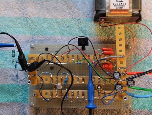
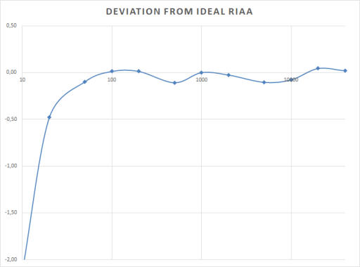
Fig. 2: Experimental setup of the input stage. A small heat
sink is mounted on the cascoding BC550 transistor (power
dissipation around 180mW).
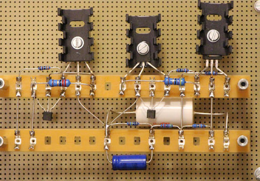
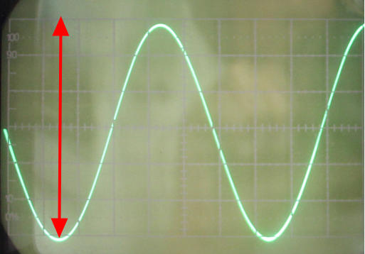
Fig. 8: Maximum voltage swing before clipping is 30V
pp
(red
arrow indicates +/- 15V on the screen).
Fig. 7: Experimental setup of the impedance converter.
Fig. 3: Measured deviations from the ideal RIAA response
(db) between 10Hz and 40kHz with MC input transformers
and output capacitor included.
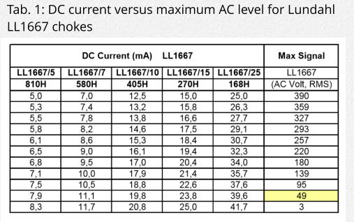
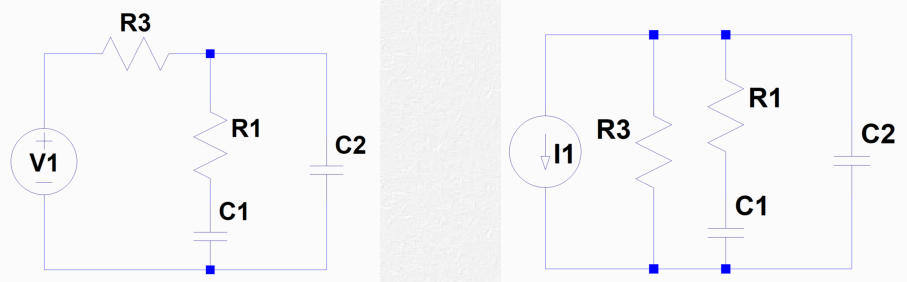
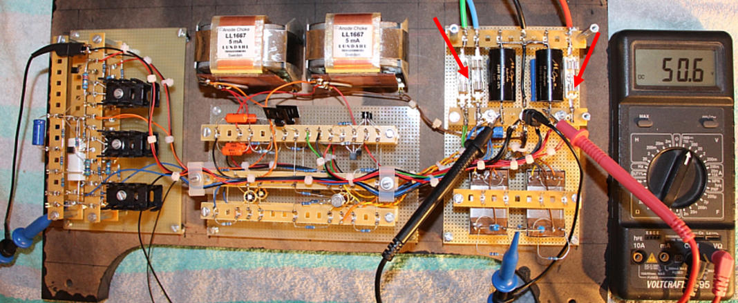
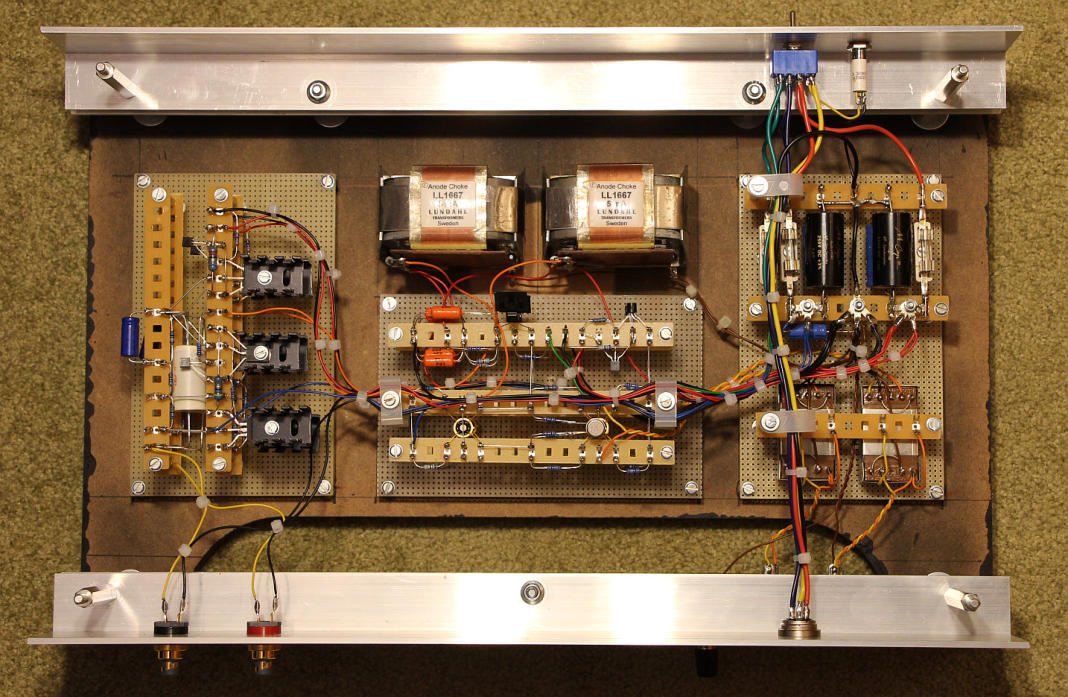
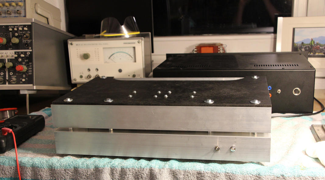
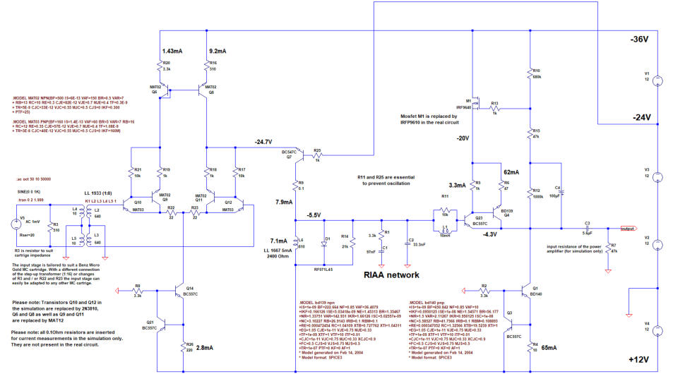
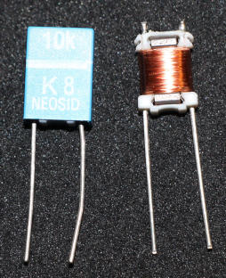
Fig. 6: 10mH Neosid choke.
super triode, vinyl, audio, analog, single ended, SE, power amplifier, hybrid, tube, KT66, 6SN7, ECC88, Mosfet, Lundahl, MC phono stage, preamplifier, MM, MC, moving coil, moving magnet, LL1693, LL1667, LL9226, LL1933, RIAA, folded
cascode, 2CS5200, MAT12, 2N3810, LL1660S, IXFN32N120P, balancing amplifier