Balancing Cathode Follower
(single-ended to push-pull)
A friend asked me to design a balancing stage to connect the asymmetrical RCA outputs of his phono stage, CD
player and internet streamer to the symmetrical XLR inputs of his active loudspeakers. It should be tube based with
input select switches and an attenuator at the front end. Output impedance of the phono stage is several hundred
ohms, input impedance of the active speakers is around 10k. There is no need for any voltage amplification.
The Circuit
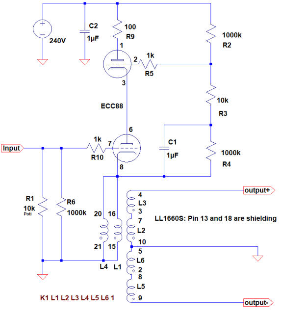
I chose a Lundahl LL1660S 10mA transformer for balancing and an ECC88 to drive the transformer as a cathode
follower. Figure 1 shows the schematic. The lower triode is the cathode follower. The ohmic resistance of the two
primary coils (coils C) is 312Ohm when connected in parallel. Therefore, the primary coils can serve as the cathode
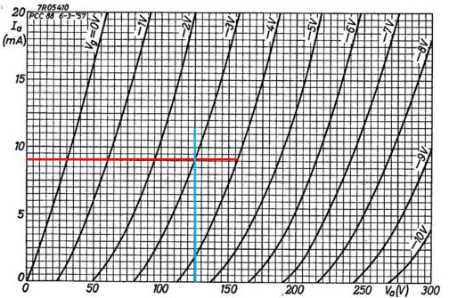
resistor to set the triode‘s operation point to 9mA (anode voltage of the lower tube being around 120V, fig. 2). The
ECC88 is designed for cascode operation with one specified triode placed on top of the other triode. The maximum
voltage allowed between the heater and the upper cathode is 150V. So there is no need to elevate the heater
potential. The upper ECC88 triode is bootstrapping the lower triode to keep its cathode to anode voltage constant
independent from the audio signal at the cathode. This is for several reasons:
•
A constant voltage between cathode and anode lowers distortion
•
Not only the cathode but also the anode follows the grid voltage. This reduces the virtual capacitances
between grid and cathode as well as between grid and anode close to zero.
•
Finally bootstrapping allows fine tuning of the idle current by adjusting the anode voltage of the lower
triode through shuffling the values of R2 and R4.
The grid resistors R5 and R10 as well as the anode resistor R9 shall avoid high frequency oscillation of the circuit. Be
aware that upper and lower triode are specified in the data sheets and may not be switched.
Fig. 2: Point of operation of the lower triode
Fig. 1. Schematic of the balancing cathode follower
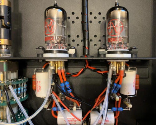
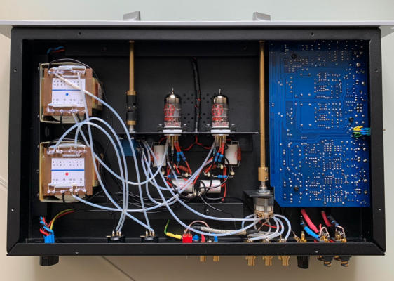
Fig. 3a and b. Circuit arrangement of the balancing cathode follower. The printed circuit board is an integrated solid state phono
stage that was replaced by the hybrid solid state / tube phono stage later on.
The Power Supply
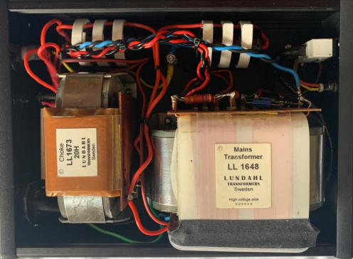
A LL1648 power transformer and a LL1673 / 20H choke were available from a former project, that never really came
to life. Surely it might be considered an overkill as a power supply for two ECC88.
As already mentioned above there is no need to elevate the heater potential as the maximum potential allowed
between heater and the upper cathode is 150V. The 47Ohm resistors achieve symmetry of the heater AC voltage
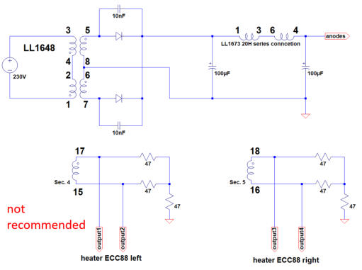
with respect to ground. The rest of the circuit is pretty much self-explanatory (fig. 4a, b and 5). It delivers 240V.
In February 2023 I learned from an e-mail exchange with Jac van de Walle that the original two-phase rectification as
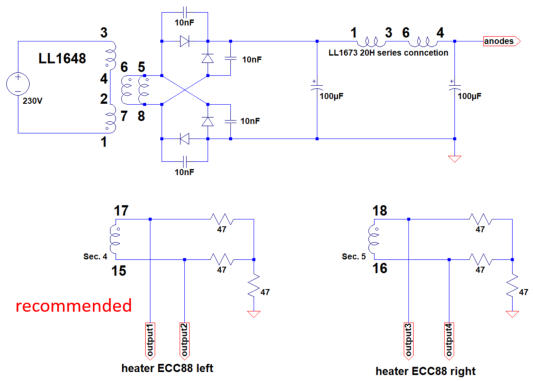
shown in figure 4a is not the best choice due to the specific Lundahl transformer architecture. The secondary coils in
figure 4a draw some DC. The better choice is a simple bridge rectifier as shown in figure 4b. So the power supply has
been changed accordingly. Surprinsingly, switching to the bridge rectification resulted in a slight but clearly audible
improvement in sound quality.
Fig. 4a: Power supply of the cathode follower (old). Fig. 4b: Power supply of the cathode follower (new).
Fig. 5: The power supply.
super triode, vinyl, audio, analog, single ended, SE, power amplifier, hybrid, tube, KT66, 6SN7, ECC88, Mosfet, Lundahl, MC phono stage, preamplifier, MM, MC, moving coil, moving magnet, LL1693, LL1667, LL9226, LL1933, RIAA, folded
cascode, 2CS5200, MAT12, 2N3810, LL1660S, IXFN32N120P, balancing amplifier