OpAmps, jFets or BjTs
Most MC phono head amplifiers are implemented as voltage controlled voltage sources ideally with an infinite input
resistance and resistors across the input to optimize the input impedance for the specific cartridge in use.
Operational amplifiers but also discrete circuits with low noise jFets suit this purpose well.
Specifically operational amplifiers are gifts from heaven for the audio industry. Their „plug and play“ option, the need
of few external components, excellent power supply rejection ratio (PSRR) and easy gain adjustment over a wide
range make operational amplifiers universal and cost effective devices and obviously they are getting better and
better. However, adverse effects of huge global feedback are still discussed controversially.
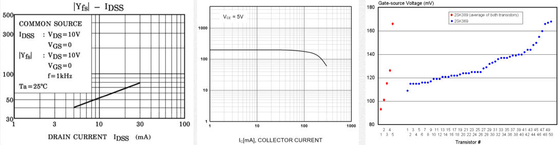
In discrete designs JFets are considered an easy option for their almost infinite input impedance, easy operation
point settings and seemingly tube like characteristics. However, jFets exhibit relatively high gate capacitances, poor
linearity and low gain compared to BJTs (fig. 1a and b). Their electrical characteristics scatter over a wide range (fig.
2).
Back to top of the page
Power supply with batteries?
“Power supplies are the hearts and the lungs of any amplifier design“ (Merlin Blencove). In our modern world we cannot
rely of our incoming power being a clean sinusoidal AC voltage of 50Hz or 60Hz. Dimmer switches, fluorescent bulbs,
LED light sources or computer power supplies introduce transients, buzz, ripple or high-frequency voltage spikes that
can make it past the AC/DC conversion inside the power supply resulting in "dirty power". Furthermore specifically
unbalanced designs show poor power source rejection ratio (PSRR) and thus are highly susceptible to transients,
noise and ripple on the power supply rails.
Problem solvers may be line filtering and audiophile (= expensive) power cords, Faraday shielding between
transformer coils, magnetic shielding, careful L-C filtering and / or shunt regulation. Holger Barske (text in German
language) designed a sophisticated balanced power supply comprising six chokes followed by shunt regulation. Rod
Elliot wrote a comprehensive article on the pros and cons of serial and shunt regulation in small current power
supplies. However, if requested voltage and current levels are low as for example in a solid state phono preamplifier
you may consider to chemically generate you own power from batteries and elegantly eliminate the "dirty power"
problem.
Back to top of the page
Active or passive RIAA equalization?
Passing a sine wave through a passive RIAA filter will reduce its amplitude but preserves its exact form. A feed-back
loop within an active RIAA filtering takes the sine wave from the output back to the input. Thus it is more prone to
distortion due to setting times, slew rates, input / output impedances and other variables. Of course there are top
notch amplifiers with active RIAA filtering but they require sophisticated engineering. For designing DIY projects
passive RIAA filtering is substantially easier to handle IMHO. Furthermore, designs without global negative feedback
loops exclude active RIAA equalization anyway.
Back to top of the page
Impedance controlled passive RIAA equalization
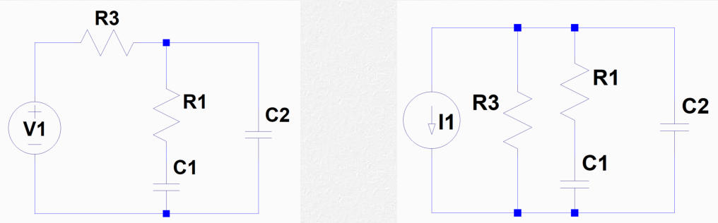
Standard passive RIAA equalization networks are driven by voltage sources such as operational amplifiers (fig. 3) and
normally comprise a voltage dividing frequency depending network. However, transistors, pentodes or cascoding
triodes are almost ideal current sources. Specifically common base circuits allow an impedance controlled network.
Thus the resistor R3 in figure 4 defines the output impedance. Contrary to R3 in figure 3 it is connected to ground
and not the direct signal path.
Fig. 3 and 4: The impedance of the voltage source is theoretically zero while the theoretical impedance of the current source is
infinite. Thus C1, R1 and C2 "see" the same impedance of R3.
Back to top of the page
Electrolyte capacitors in the direct signal path
The suitability of electrolyte capacitors in audio gear is discussed controversially. Distortion increases with the signal
voltage across the electrolyte capacitor. If the capacitance is large enough to push the cut-off frequency into the sub
1Hz region, the signal voltage across the capacitor becomes negligible. Furthermore it is advantageous to apply a
polarising voltage below 10V. Merlin Blencove and Douglas Self explain this extensively in their textbooks.
Back to top of the page
MC step-up transformers
MC step-up transformers are problem solver in many ways. They elevate the tiny MC signal to more convenient levels
without adding noise. They break up ground loops. They protect expensive cartridges from being burned out by
front-end failures. Furthermore, a transformer allows asymmetric to symmetric or symmetric to asymmetric
connections. Transformers are bulky and they are expensive. If that is an issue one might restrain from their use. By
the way, NEVER use a digital multi-meter to check the transformer wiring for its core may be magnetized
permanently (information taken from the JAC-Music website).
Back to top of the page
Back to Main Page

super triode, vinyl, audio, analog, single ended, SE, power amplifier, hybrid, tube, KT66, 6SN7, ECC88, Mosfet, Lundahl, MC phono stage, preamplifier, MM, MC, moving coil, moving magnet, LL1693, LL1667, LL9226, LL1933, RIAA, folded
cascode, 2CS5200, MAT12, 2N3810, LL1660S, IXFN32N120P, balancing amplifier
Some Basic Thoughts
OpAmps, jFets or BjTs
Power supply with batteries?
Active or passive RIAA equalization?
Impedance controlled passive RIAA equalization
Electrolyte capacitors in the direct signal path
MC step-up transformers
Back to Main Page