Nashville SE 20 - the modified SuperTriode Concept
Fig. 1 shows a modification of the SuperTriode concept for a 25W SE hybrid power amplifier that was transferred
into a real life project.
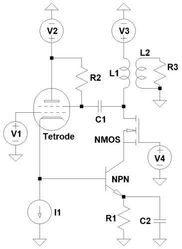
Fig. 1: modified concept for a hybrid
tube / solid state SE power amplifier
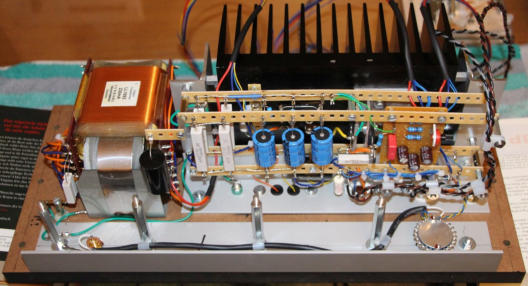
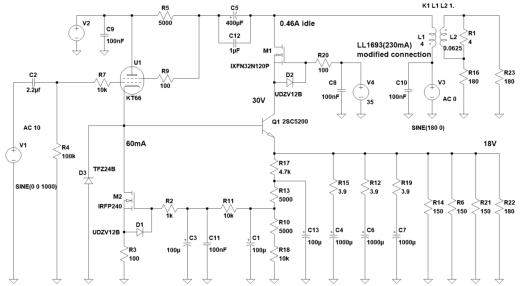
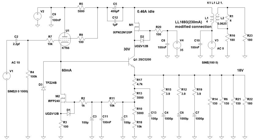
Fig. 2: Schematic and picture of the SE hybrid power amplifier (click to enlarge). Additional picture here.
The Output (Power) Stage
The driving Tube
The KT66 beam power tetrodes had been the output tubes in legendary amplifiers such as the QUAD II and thus
have an excellent reputation from past times. Their parameters are almost ideal for the SE hybrid amplifier
project. The plate current is set to 60mA, the plate voltage is around 300V. Voltage at the cathode is +18V. The
IRFP240 MosFet serves as an adjustable current sink to load the cathode. The plate dissipates around 17W
(maximum plate dissipation allowed is 25W). R7 and R9 are grid stoppers to prevent parasitic oscillation.
I considered the EL34 as an alternative to the KT66. As a real pentode the EL34 has a suppressor grid to repel
electrons from secondary emission back to the plate. Beam power tetrodes achieve the same effect by beam-
focusing plates and careful alignments of both the control grid and the screen grid. Although more prone to
oscillation beam power tetrodes have substantially less screen grid current due to its specific grid design and that
was an important issue. High screen grid current would require a low resistor R5 and thus an even larger
capacitor C5 within the local feedback loop.
The current amplifying BJT
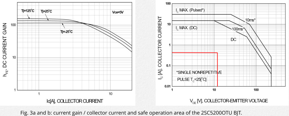
The tube works as a cathode follower and drives a 2SC5200OTU power BJT from ON semiconductors which
obviously is the successor of the Toshiba 2SC5200. Its current gain h
FE
is around 100 (fig. 3). Thus the base needs a
current swing of +/- 5mA (p-p) for a full current swing from 0mA to 1000mA at the collector. The current gain /
collector current function of this power transistor shows good linearity and a continuous function up to 2A (fig.
3a). The BJT is cascoded by a rugged industrial power MosFet IXFN32N120P. It keeps the BJT at a comfortable 12V
between emitter and collector (fig. 3b) and eliminates the Miller effect that would increase the 200pF input
capacitance between base and collector. The idle collector current is set to 460mA by the +18V at the KT66
cathode and the BJT emitter resistors. The three bypassing 1000µF capacitors are in series with one small 3.9Ohm
resistor each to achieve an equal current distribution among the capacitors and to linearize the BJT by some local
feedback.
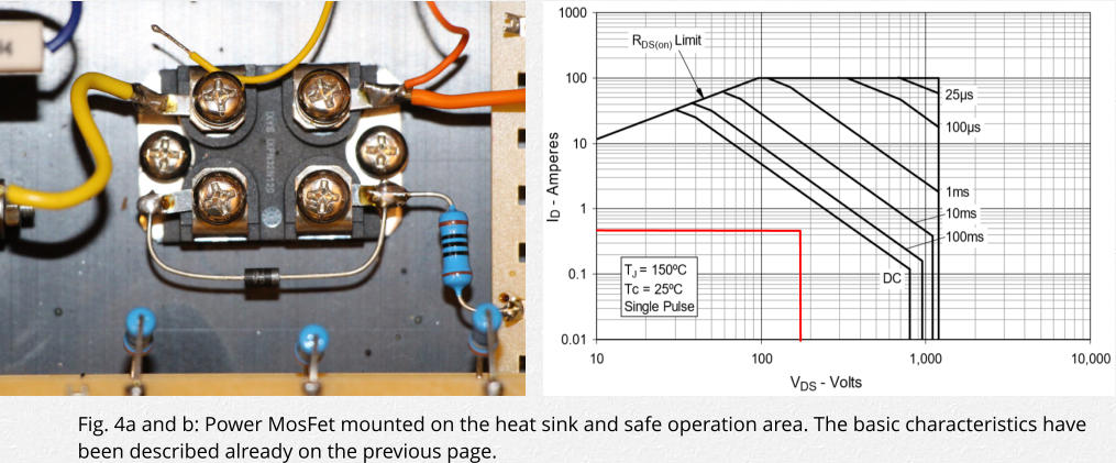
The cascoding MosFet
The cascoding IXFN32N120P can stand 1000W maximum power dissipation (case temperature 25°C) and voltage
peaks up to 1.2kV. In the circuit it takes around 80W power loss. Its heat sink should have a thermal impedance of
at least 0.4K/W. I used Fischer SK520 heat sinks (200 x 83 x 150mm, 0.35K/W). The transistor chip is isolated
internally. So no washer is needed between case and heat sink. With passive cooling the heat sink temperature at
the fins is around 35°C above the ambient room temperature after one hour of operation. 100Ohm at the
MosFet‘s gate prevents parasitic oscillation (fig. 4). A 12V Zener diode protects the gate.
Local Feedback
The output signal at the MosFet‘s drain is fed back into the screen grid of the KT66 power tetrode. For an
appropriate operation the KT66 voltage at the plate is around a constant 300V while voltage at the screen grid is
270V. Voltage swing at the screen grid is from 160V to 380V (p-p) for the voltage swing at the MosFet‘s drain is
220V p-p at full power. An electrolyte capacitor was unavoidable in the local feedback signal path for the solid
state section runs at 180V only. However, it is bypassed by a high quality audio cap. The resulting local negative
feedback is 20db. Input voltage required for 20W into 4Ohm is 10Vrms. Without any feedback into the screen grid
the input voltage for 20W is 1Vrms. To keep the circuit as straight and simple as possible I restrained from any
feedback from the secondary coils of the output transformer to minimize phase shift and to avoid the necessity of
compensatory RC networks .
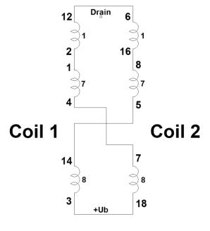
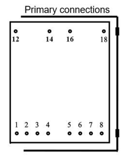
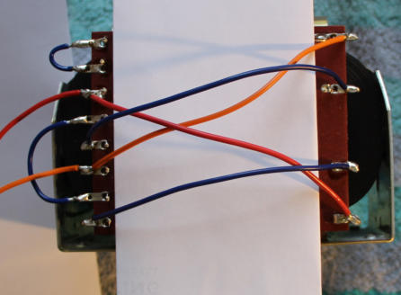
Modified LL 1693 Output Transformer
As already mentioned above the primary coils of the output transformer are connected in parallel (see fig. 5 to 7
below). This allows twice the recommended idle current of 230mA (see Lundahl datasheet) while the core‘s
magnetic flux density remains unchanged.
Fig. 5, 6 and 7: LL 1693 primary winding connection for 250Ohm primary load impedance (secondary Alt B).
The primary inductance drops from 16H to 4H. The reflected primary impedance drops from 1kOhm to 250Ohm.
With twice the idle current and half the voltage at the cascoding MosFet‘s drain the operating points are more
transistor friendly. According to the LT spice simulations the circuit delivers around 25W into 4Ohm taking into
consideration all copper resistances of the output transformer. The secondary coils are not connected to ground
directly but through two 180Ohm power resistors at both ends to damp potential resonant circuits from
transformer stray inductances or stray capacitances. In the unlikely event of a short cut between primary and
secondary coils the resistors will draw a current of 180V / 90Ohm = 2A. That will cause an immediate blow of the
1.5A fast-blow fuse in the 180V section of the power supply.
The Cathode Current Sink
The IRFP240 MosFet is the usual current sink to set the operation point of the KT66 to 60mA. Its gate senses the
voltage drop at the BJT emitter through a R-C-R-C-R-C low pass filter and stabilizes the idle current of the 2SC5200
at 460mA. Resistors R10 and R13 in the schematic are a 10k trim potentiometer in real life to adjust the BJT
current to 460mA exactly. The low pass filter prevents the audio signal from being fed back into the MosFet‘s gate
(-60dB @ 10Hz). However, the values of the filtering resistors R11, R13, R17 and capacitors C1, C11 and C13 are
carefully chosen for the following reasons:
Switching on the Real Life Circuit
A DC coupled tube-transistor circuit may work nicely in the simulation but it should be considered carefully what
happens if the tube is cold and the circuit is switched on.
At t = 0 all voltages are zero and the tube‘s cathode is cold. One or two seconds after switching on the plate and
drain voltages are at their preset values, the tube‘s cathode just starts getting warm and the IRFP240 gate voltage
is still zero. Thus both tube and MosFet as well as the other transistors are not conducting any current. Seconds
later the cathode gets hotter and the tube starts drawing current through the base-emitter diode of the 2SC5200
and its emitter resistors. Collector current will start immediately and this will rapidly increase the voltage drop at
the emitter resistors. The increasing voltage drop passes through the R-C-R-C-R-C low pass filter to the IRFP240
gate and the MosFet starts conducting, settling the tube operation point and the circuit is ready to play.
However, there is a time delay between the rising BJT collector current and MosFet taking over the tube‘s cathode
current. That time delay is crucial and set by the values of the R-C-R-C-R-C low pass filter (R17, C13, R13, C1, R11,
C3). If the filter is passing through voltage changes too slowly the 2SC5200 and the cascoding IXFN32N120P will
draw too much current and burn out before the IRFP240 is is able to take over the tube‘s current. If the filter is
passing through voltage changes at the emitter too fast unwanted low frequency audio signal is fed back into the
MosFet. The 24V Zener diode is an additional safety measure to limit the maximum cathode / base voltage to 24V
and thus the current through the transistor to (24V - 0.7V) / 39Ohm
emitter resistor
= 0.6A.
The values in the schematic work nicely for the KT66 and should be suitable for other „big bottle“ tubes such as
the EL34, 6L6, KT88 or 6550 also. In smaller tubes cathodes might heat up faster and either capacitances or
resistances of the low pass filter must be reduced.
•
The current delivering transistor is a power BJT and
it is cascoded by a high power MosFet.
•
The tube‘s plate current is decoupled from the
output transformer coils.
•
Tube and transistors have independent voltage
supplies (V2, V3).
•
The wiring of the LL1693 primary coils is modified
to lower the reflected impedance from 1k to
250Ohm.
•
The power triode from the original concept is
substituted by a beam power tetrode.
•
The audio signal from the primary transformer coil
is not fed back into the plate but into the screen
grid through capacitor C1.
super triode, vinyl, audio, analog, single ended, SE, power amplifier, hybrid, tube, KT66, 6SN7, ECC88, Mosfet, Lundahl, MC phono stage, preamplifier, MM, MC, moving coil, moving magnet, LL1693, LL1667, LL9226, LL1933, RIAA, folded
cascode, 2CS5200, MAT12, 2N3810, LL1660S, IXFN32N120P, balancing amplifier