Laboratory Page Nashville SE 20
•
Calculation of Output Impedance
•
Measured Output Impedance
•
Measured Frequency Response
•
Measured Output Power
Back to Main Page
Calculation of Output Impedance
For a better estimation of the interaction between speakers and a tube power amplifier sometimes it might be
useful to measure the tube amplifier output impedance. A very simple method requires two resistors, an AC
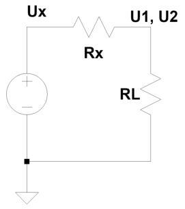
voltmeter and some basic calculations. Figure 1 shows the experimental setup.
Any power amplifier can be seen as a voltage source (U
X
) with a resistor
R
X
in series. R
X
resembles the amplifiers‘s output impedance. Even in
high power amplifiers with huge global feedback R
X
might be very
small but rarely will be zero. R
L
is the load, U
1
and U
2
are the output
voltages to be measured with varying load resistor values.
Fig. 1: Basic setup to measure
output impedance.
EQ 1 and 2 describe the relation between resistor values and voltages.
U
X
/ U
1
= (R
X
+ R
L
) / R
L
(equation 1)
U
X
= (R
X
+ R
L
) * U
1
/ R
L
(equation 2)
R
L
is known and U
1
is measured. However, the equations contain the two unknown variables U
X
and R
X
. To solve
this problem R
L
is multiplied by the factor a for a second measurement which introduces U
2
and gives
U
X
/ U
2
= (R
X
+ aR
L
) / aR
L
(equation 3)
U
X
= (R
X
+ aR
L
) * U
2
/ aR
L
(equation 4)
U
X
disappears by substituting U
X
in EQ 2 by the right side of EQ 4 which gives
(R
X
+ aR
L
) * U
2
/ aR
L
= (R
X
+ R
L
) * U
1
/ R
L
(equation 5)
R
L
cancels out which leaves
(R
X
+ aR
L
) * U
2
/ a = (R
X
+ R
L
) * U
1
(equation 6)
Multiplication on both sides of EQ 6 reverals
R
X
* U
2
/ a + R
L
* U
2
= R
X
* U
1
+ R
L
* U
1
(equation 7)
Subtracting R
X
* U
1
and R
L
* U
2
on both sides of EQ 7 reverals
R
X
* U
2
/ a - R
X
* U
1
= R
L
* U
1
- R
L
* U
2
(equation 8)
R
X
* (U
2
/ a - U
1
) = R
L
* (U
1
- U
2
)
(equation 9)
Thus output impedance R
X
equals
R
X
= (R
L
* (U
1
- U
2
)) / (U
2
/ a - U
1
)
(equation 10)
R
L
is known and both U
1
and U
2
are measured. For measurement of U
2
R
L
is multiplied by the factor a. EQ 10
can easily be programmed into an EXCEL table for measurement series. Let us briefly check whether EQ 10 is
correct:
If U
X
is 10V, R
X
is 9Ohm and R
L
is 1Ohm U
1
must be 1V according to
U
X
/ U
1
= (R
X
+ R
L
) / RL
10 / 1 = (9 + 1) / 1
10 = 10
If R
L
is changed from 1Ohm to 3Ohm (a = 3) U
2
must be 2.5V according to
U
X
/ U
1
= (R
X
+ R
L
) / R
L
10 / 2.5 = (9 + 3) / 3
4 = 4
Determination of R
X
from EQ 10 with U
1
= 1V, U2 = 2.5V and a = 3
reveals
R
X
= (R
L
* (U
1
- U
2
)) / (U
2
/ a - U
1
)
R
X
= (1 * (1- 2.5)) / (2.5 / 3 - 1)
R
X
= - 1.5 / -0.1666667
R
X
= 1.5 * 6
R
X
= 9
which equals the preset value of R
X
.
Output Impedance Nashville SE 20
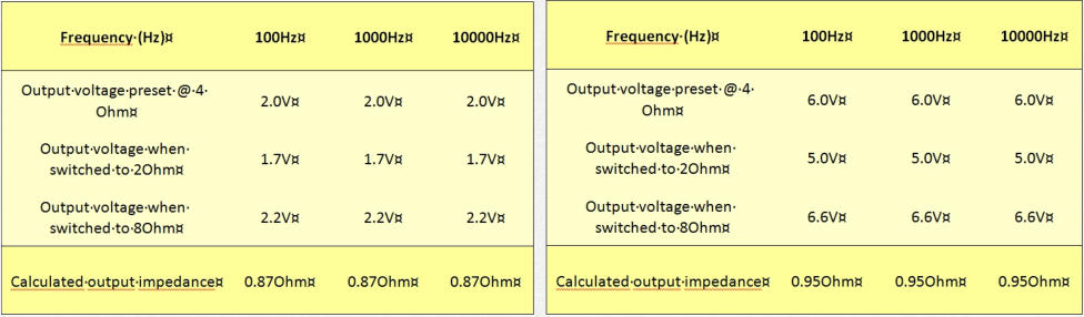
Output impedance was measured at 1W output power (2V@4Ohm, table 1a) and 9W output power (6V@4Ohm,
table 1b) at 100Hz, 1000Hz and 10kHz according to the above equation 10. The following two tables show the
results. Output impedance is around 1Ohm and almost constant with respect to frequency and output power.
Table 1a and b: calculated output impedance at 1W and 9W output power into 4Ohm.
Simplified the output impedance is given by three resistances in series: output impedance of the plain tetrode-
BJT-MosFet circuit plus the primary coil resistance of the output transformer plus its secondary coil resistance.
Secondary coil resistance is 0.2Ohm, reflected primary coil resistance is 0.24Ohm (15Ohm copper resistance
divided by the transformer impedance ratio 250Ohm / 4Ohm). This leaves roughly 0.6Ohm reflected
impedance for the circuit itself. Multiplied with the transformer impedance ratio the output impedance of the
tetrode-BJT-Mosfet circuit is a surprisingly low 40Ohm.
Back to top of the page
Frequency Response Nashville SE 20
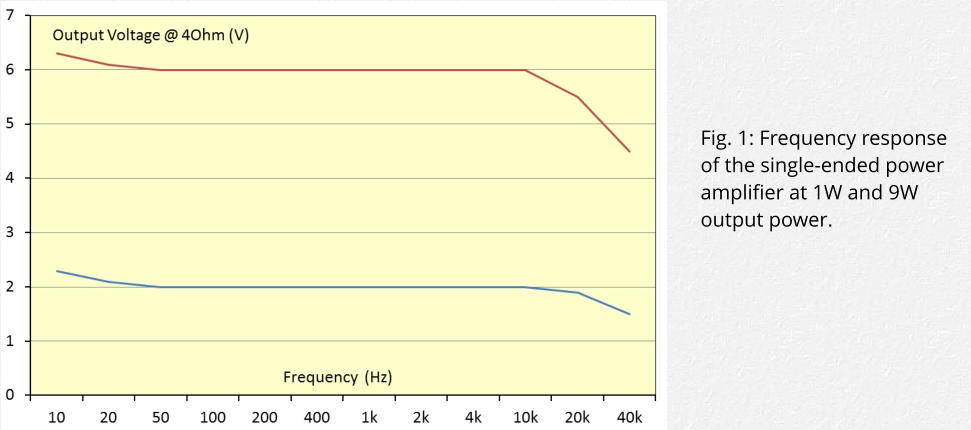
Frequency response was measured at 1W output power (2V@4Ohm) and 9W output power (6V@4Ohm) from
10Hz to 40kHz. Figure 1 shows the results. Below 20Hz the output voltage increases slightly probably due to the
limited capacitance of the capacitor in the feedback loop. At 20KHz voltage drop is 0.4db (1W) and 0.75db (9W).
At 40KHz voltage drop is 2.5db (1W and 9W) probably due to limits of the output transformer.
Unfortunately the Lundahl data sheet on the LL1693 does not provide data on the inherent frequency
response. However, for a bulky high power audio transformer for single ended application the frequency
response of the LL1693 can be considered excellent.
Output Power Nashville SE 20
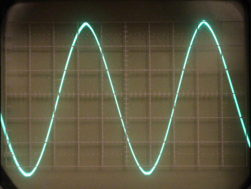
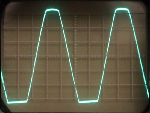
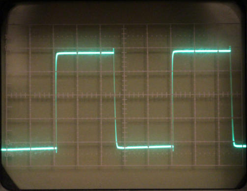
Output power was measured using a 4Ohm load resistor at 1kHz with a trusty old analog oscilloscope. Figures
1 to 3 show three screenshots from the oscilloscope just before clipping (fig. 1), with clippping (fig. 2) and the
1KHz square wave response (fig. 3). The scale on the screen is 5V/cm. Thus the sine wave is just above 30V
peak to
peak
before clipping.
From figure 1maximum voltage swing of + / -15V was assumed. Thus the real maximum output power at 1kHz
is U
2
/ R = (15 / square root 2)
2
/ 4 = 28W.
Fig. 1: Maximum voltage swing of the amplifier output into Fig. 2: Clipping above 30V
peak to peak
voltage swing.
4Ohm. The red arrow indicates the scale of +/- 15V
on the screen of the oscilloscope
Fig. 3: Square wave response (1kHz) at +/- 10V with slight
overshoots.


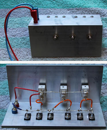
Power Load resistor with variable resistance
switchable between 2Ohm and 16Ohm
Super triode, vinyl, audio, analog, single ended, SE, power amplifier, hybrid, tube, KT66, 6SN7, Mosfet Lundahl, phono stage, MM, MC, moving coil, moving magnet, LL1963, LL1667, LL9226, LL1933, RIAA, phono.
.