Prototype Phono Stage Il Trovatore
This phono stage has been transferred to the old projects section
because the 2SK369 jFets obviously are out of production
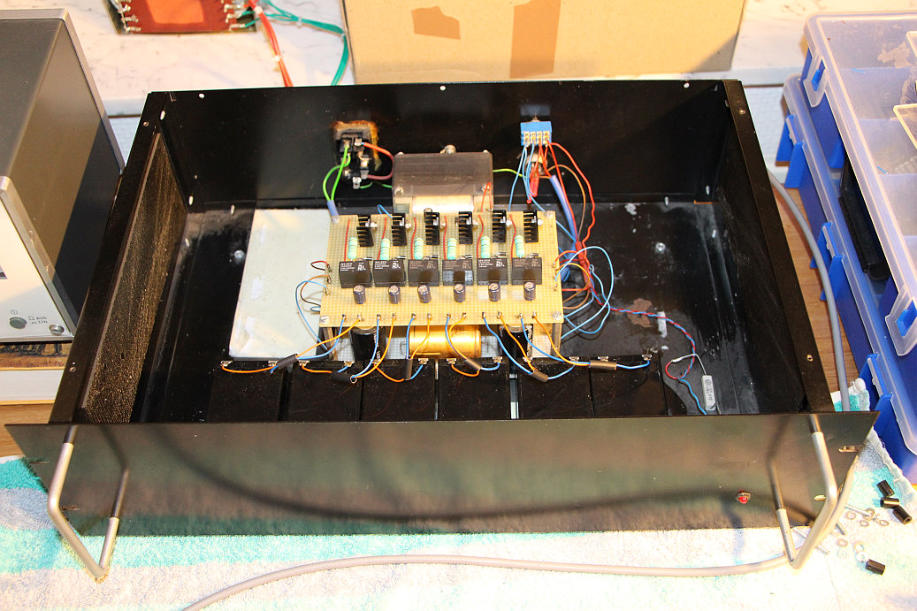
Fig. 1. Prototype of the Phono stage Fig. 2: Phonostage schematic (click to enlarge)
The Concept
The approach for the phono stage was the following:
•
No feedback except for local feedback by degeneration resistors and thus a discrete circuitry and passive RIAA
•
accumulator based power supply and thus the necessity of solid state devices (of course also a conventional
power supply is also possible)
•
cost effectiveness (at least to a certain extent)
A no-feedback design requires linear active components. Years ago Nelson Pass wrote in his article on cascode
amp design: „ . . in real life, the gain of a transistor, tube or FET changes as the voltage across the devices changes and
as the current through the device changes. As these conditions fluctuate, the device creates distortion, but if we hold these
conditions to a constant, the device becomes distortionless.”
In phono preamplifiers tubes can be considered inherently linear as only a minuscule proportion of their voltage
swing headroom is used. Thus currents and voltages are kept almost constant, meeting Nelson Pass’s statement.
Surprisingly enough even high prized tube phono stages (i.e. Allen Wright, K&K Audio or Audio Design Guide) use j-
FETs in their input stages. Modern j-FETs such as the 2SK369 provide very low noise and high transconductance.
On the other hand their linearity is poor compared to BJTs, not to mention tubes. However, to keep distortion low,
j-FETs may be selected for a high negative VGS at a desired idle current to achieve current feedback through a
source resistor. Cascoding the j-FET with a tube isolates the transistor from the high voltage and allows a high load
resistor ensuring sufficient gain (gm
FET
x R
Load
) while keeping the j-FET voltage constant and its current change low,
a nice approach to merge the advantages of tubes and FETs.
Trying to transfer this concept into the world of transistors is pretty much limited by the maximum voltages of low
noise transistors (typically 30 to 50V) excluding the option of high idle currents plus high load resistors. However, a
suitable idle current of the j-FET plus a high load resistor can be achieved using a folded cascode design for it
allows independent idle currents for the amplifying common source j-FET and the cascoding BJT. A 2SK369 works
nicely around 5mA and a BC560 works nicely at 1mA. Hence the load resistor value can be multiplied by five
compared to a standard common source or standard cascode design and the amplification is increased
accordingly.
The Circuit
The phono amplifier consists of two amplifying stages. The first stage might be considered a single-ended
differential design. The Lundahl LL 9226 step-up transformer is set to a moderate 1:5 turns ratio (termination A in
the Lundahl datasheet) to suit my Benz Micro Gold cartridge. Basically it serves two purposes: transforming the
tiny 0.4mV signal to a more convenient 2mV without adding noise and to protect expensive cartridges from being
burned out by front end failures. Furthermore, the transformer allows a symmetric connection between turntable
and preamplifier if needed. By the way, NEVER use a digital multi-meter to check the transformer wiring for its
core may be magnetized permanently (taken from the JAC-Music website).
The two 2sk369 operate at 5.6mA each. A differential design was chosen for the following reasons:
Cancellation of k2 distortion (although cancellation is not perfect due to different resistor values R3 and R4 in
the current mirror)
Cancellation of idle current fluctuations due to j-FET temperature changes.
Higher gain: the second j-FET feeds the signal into the current mirror. The gain of the input stage is around
46db.
Input Stage
The current mirror emitter resistors R3 and R4 are set to 1000 and 1220 Ohm. If J2 feeds 5.6mA into the current
mirror, Q3 sources a total of 6.8mA. J1 takes 5.6 mA leaving 1.2 mA idle current for the cascoding Q2. R4 may need
some tweaking to adjust the idle current of Q2 to 1.2 mA. R6 and R7 set the drain of Q2 to 9.3V. The oscilloscope
showed a better square wave response when both resistors were bypassed with capacitors (fig. 3).
Fig. 3. Input stage with MC transformers Fig. 4: Output stage with cooling fins for thr BJTs
Passive RIAA
The RIAA network simply is a frequency dependent load of the cascoding transistor Q2 lacking the typical voltage
dividing first resistor of conventional passive RIAA networks. Thus the RIAA network impedance controls the gain
without a resistor in the primary signal path.
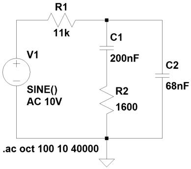
Standard passive RIAA equalization networks are driven by voltage sources such as operational amplifiers (fig. 5)
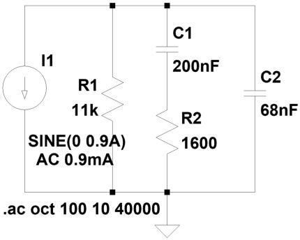
and normally comprises a voltage dividing frequency depending network. However, transistors are (almost) ideal
current sources, specifically in common base circuits and allow an impedance controlled network (fig. 6). Thus the
resistor R2 defines the cascode output impedance and is connected to ground and not the direct signal path.
Further advantages of the impedance controlled network can be found here.
Fig. 5 and 6: The impedance of the voltage source is theoretically zero while the theoretical impedance of the current source is
infinite. Thus C1, R1 and C2 "see" the same impedance of 11k. Click on figures for RIAA equalization curves.
Output Stage
The basic configuration of the second stage is quite similar to that of the the first. The pair of j-FETs in the first
stage is replaced by two Sziklai pairs comprising a j-FET and a bipolar transistor again with the scope to minimize
current changes in the j-FET transistors. Idle currents are higher to suit the 1k resistor at the collector of Q10. Q4,
Q9 and Q10 may require some cooling because of the elevated idle currents (fig. 4).
With 0.4 mV at the input, the phono stage delivers 1.0 V at the output (@1000Hz). The RIAA response is within a
range of +/- 0.15 db from the theoretical RIAA.
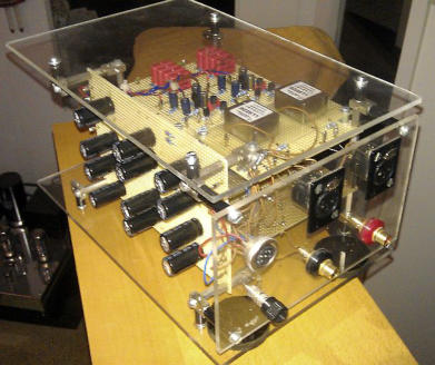
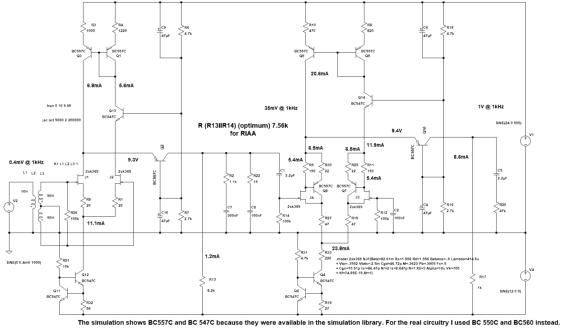
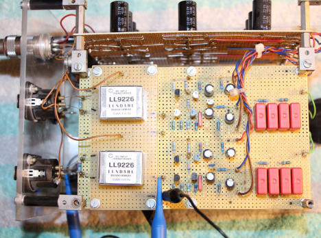
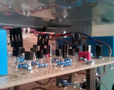
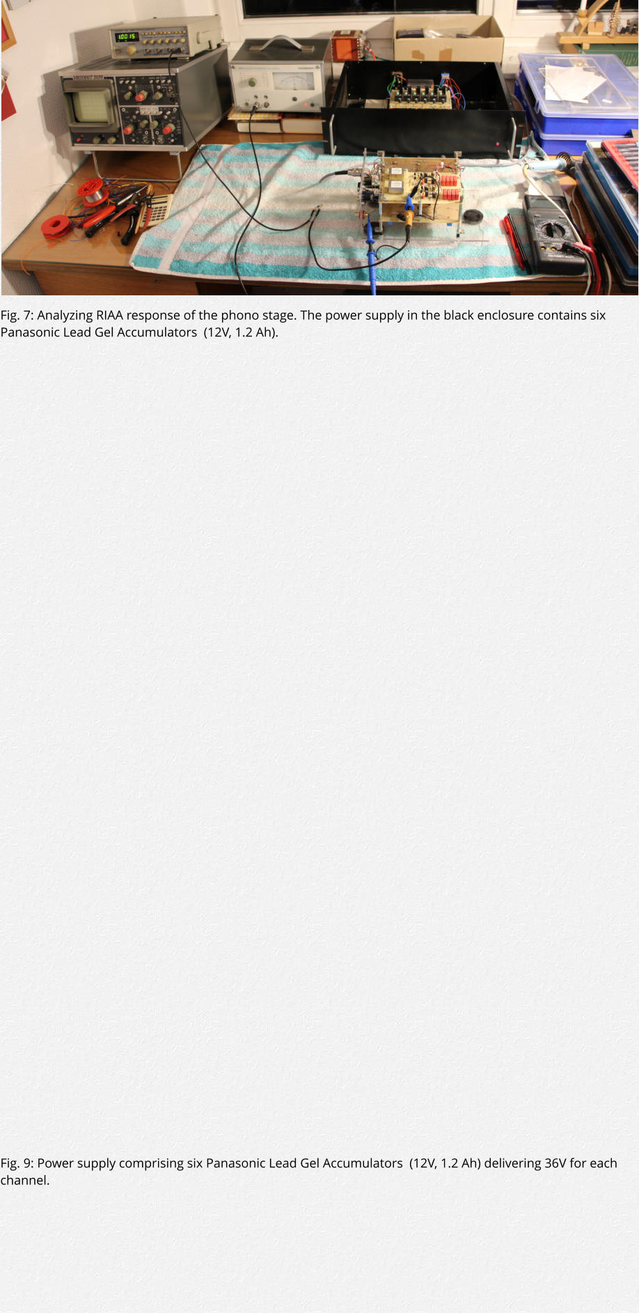
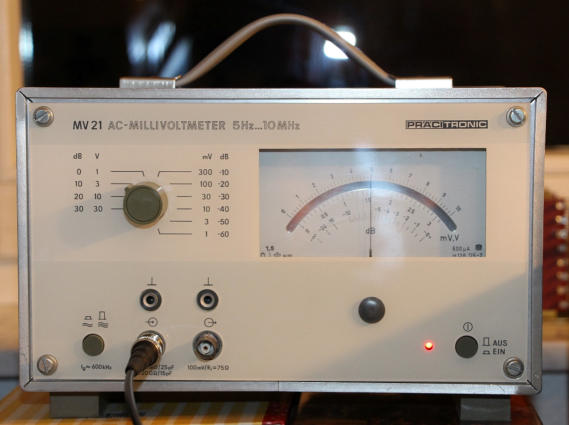
Fig. 8: Precision measuring instruments
from the former German Democratic
Republic.
super triode, vinyl, audio, analog, single ended, SE, power amplifier, hybrid, tube, KT66, 6SN7, ECC88, Mosfet, Lundahl, MC phono stage, preamplifier, MM, MC, moving coil, moving magnet, LL1693, LL1667, LL9226, LL1933, RIAA, folded
cascode, 2CS5200, MAT12, 2N3810, LL1660S, IXFN32N120P, balancing amplifier